Posts

Transformer Design - IEC Vs ANSI/IEEE
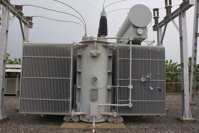
Image
    TRANSFORMERS DESIGN PARAMETERS IEC ANSI/IEEE For transformers up to 10 MVA, values of rated power roughly follow the R-10 series [3] given in ISO 3 (1997), preferred numbers : (…100, 125, 160, 200, 250, 315, 400, 500, 630, 800, 1000, 1250, etc.) Reference ANSI / NEMA C57 standard for power and distribution transformers, Standard ratings for different cooling methods OA / FA 55 / 650 C, and for standard impedance. Commonly International practice is to use Sealed tank transformers up to 1600 kVA and Conservator type for larger transformers American typical common practice in Petroleum & Chemical (P&C) applications is to use sealed tank transformers up to 15-20 MVA and conservator type for larger transformers. Shall be capable of sustaining a maximum of 105% rated Volts/Hz continuously without damage Shall sustain 110% Volts/Hz at no-load and shall be able to deliver rated power at 110% of the rated secondary voltage at a

CONVERSION OF NEMA ENCLOSURE TYPE NUMBERS TO IEC CLASSIFICATION DESIGNATIONS

Image
NEMA ENCLOSURE TYPE NUMBER DESCRIPTION IEC ENCLOSURE CLASSIFICATION DESIGNATION 1 General purpose IP10 2 Drip proof protection against falling water and dirt IP11 3 Dust & rain tight protection against windblown dust, rain & sleet & damage from formation of ice IP54 3R Rain proof & ice/sleet proof protection against falling rain & damage from formation of ice IP54 3S Dust , rain tight & ice sleet proof protection against sleet & damage from formation of ice IP54 4 Water tight and dust tight IP56 / IP66 4X Water tight and dust tight & corrosion resistant protection, hose directed water and damage from formation of ice IP56 / IP66 5 Dust tight and drip tight protection against dust, fibers, falling dirt, and dripping non corrosive liquids IP52 6 Temporary submersion protection against falling dirt, dust, fibers, hose directed water and temporary submersi

For Heat Tracing Design - Sample Heat Loss Calculation for 450 MM NB Pipe

Image
Formula: q = 2∏K x (Tm-Ta) / ln(D2/D1) q = Heat loss per unit length of pipeline (W/mtr.) Tm = Maintenance Temperature (deg. C) Ta = Minimum Ambient Temperature (deg. C) D1 = Diameter of pipe (mtr) D2 = Diameter of pipe including Insulation thickness (mtr) K1 = Thermal Conductivity of Insulation material evaluated at its mean temperature (W/m .deg.K) Sample Calculation: Pipe Size (OD) = 457.2 mm Maintenance Temperature (Tm) = 40 deg. C Min. Ambient Temperature (Ta) = -0.7 deg. C Insulation Material = Mineral Wool Thermal Conductivity of Insulation at mean temp. 65 deg. C (K) = 0.038 W/m. deg. C Insulation Thickness (t) = 45 mm Diameter of Pipe (D1) = OD of Pipe = 457.2 mm Diameter of Pipe including Insulation thickness (D2) = D1+2t = 547.2 mm Putting the above values in heat loss formula, we have Heat loss/mtr of pipeline (q) = 54.08 Watts Heat loss/mtr of pipeline with 10% design Margin = 59.5 Watts Hence to compensate the required hea

VBA Code To Unlock A Locked Excel Sheet

Image
If you have ever forgotten a password for one of your excel worksheets you know how frustrating that can be. The code used in this instruction is one of the simplest I've found. It will generate a usable code that will unlock your protected sheet. I can't take credit for the code as I merely found it in a moment of need (and I can not find where the site is anymore)... sooo I wont be much help if it doesn't work for you but I've had success with it and thought I'd share. Step 1: Open VBA Open the worksheet you forget your password to. Use Alt+F11 to enter the macro editor. Once in VBA double click the sheet you need to unlock from the menu listing on the left. This will open the general declarations page for the sheet. Step 2: Cut And Paste The Code Breaker Insert the code below in the general declarations page you have opened. You should not have to change anything , sheet name etc... Just cut and paste. _______________________ Sub PasswordBreak

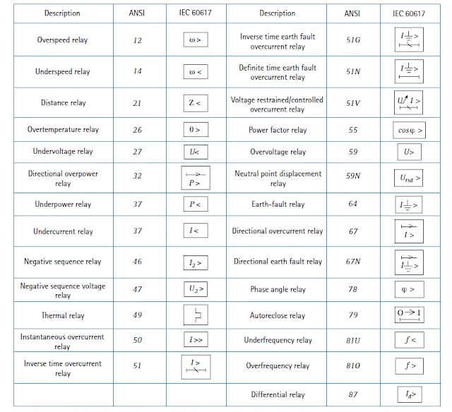
ANSI & IEC Relay Symbol

Image

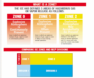
IEC Vs NEC Hazardous Area Classification Comparison

Image

Cable Sizing for High Voltage Motor

Image
Cable Sizing for High Voltage Motor Minimum Size of Cable required to withstand short-circuit : Minimum Cross Section Area of HV Cable = (If x √t)/k Where, Maximum Fault level at 6600 V - 457 MVA (Assumed) If = 40 kA at 6.6kV k = Material Constant = 0.094 (for aluminium cables) t = Fault withstand time in sec. = 0.25 sec (Assumed) Minimum Cross Section Area of HV Cable = (40 x √0.25)/0.094 = 212.76 mm2 Next available standard size is 240 mm2 Hence, minimum cross sectional area for HV cables is 240 sq. mm Now, we have to check three parameters : a)Able to withstand continuous current rating b)Voltage Drop (During Normal Running Condition) c)Voltage Drop (During Starting Condition) a)Able to withstand continuous current rating : Rating = 210 kW Power Factor = 0.88 Efficiency = 93% Rated current = 210 / (√3 x 6.6x 0.88 x 0.93) = 22.44 Amp Required current rating of cable, after adjusting for derating factor (Derating factor is explained at bottom)